
What a PLC actually does between one millisecond and the next
Contents
Every automation course starts in the same place: a PLC on the bench, a laptop,
and a diagram that looks like nothing else in software. Rungs. Contacts. Coils.
If you have written Python or C, ladder logic looks like a step backwards — a
picture of a circuit pretending to be a program.
It isn't. Once you know what a PLC is actually doing between one millisecond
and the next, the diagram stops being strange and starts being the clearest
possible description of the job.
The scan cycle is the whole idea
A PLC does not run your program the way a computer runs an application. It runs
it in a loop, forever, and every pass through that loop has three parts:
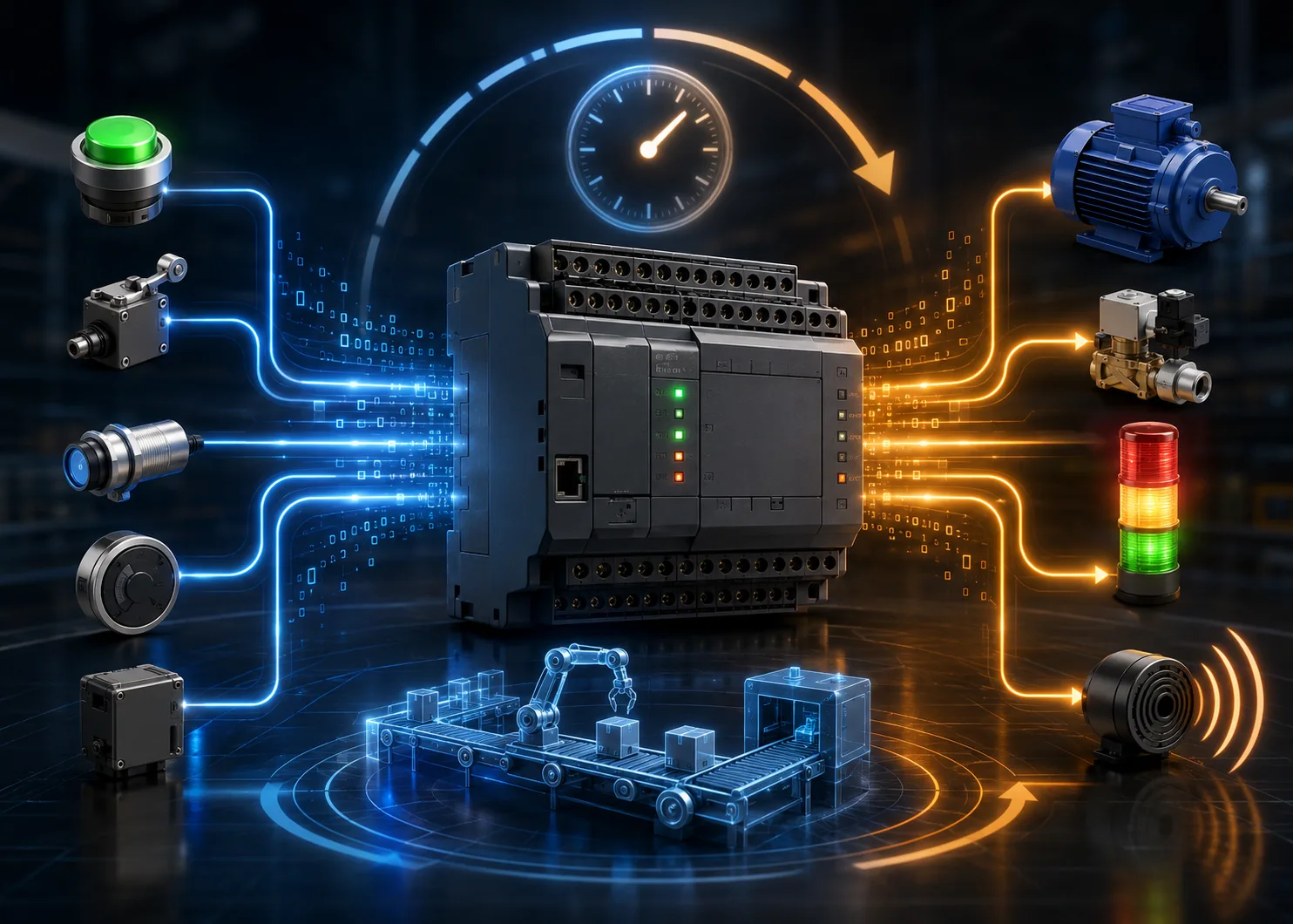
- Read every input. Every sensor, switch and limit is sampled and copied into memory. Not read when your logic asks for it — read once, all at once, before any logic runs.
- Solve the logic. Your program executes top to bottom against that snapshot. The real world can change while this happens; the PLC does not care, because it is working from the copy.
- Write every output. All the results are pushed to the physical outputs together, at the end.
Then it starts again. A small PLC might complete that loop in two to ten
milliseconds.
The snapshot is the point. Your logic sees one consistent picture of the machine, frozen at the instant the scan began.
That single design decision is why industrial control is predictable enough to
put safety-critical machinery behind. In a general-purpose program, a value can
change halfway through a calculation because something else wrote to it. In a
PLC scan, it cannot.
Why the diagram looks like a circuit
Ladder logic is drawn the way it is because it was designed to be read by
people who had spent their careers reading relay panels.
Before PLCs, control logic was physical: rows of electromechanical relays, each
one clicking in and out, wired so that current reaching the end of a rung
energised a coil. Changing the logic meant rewiring the panel. When the PLC
arrived in 1969, the people who had to trust it were the ones who had
maintained those panels — so the programming language was made to look exactly
like the wiring diagrams they already knew.
That heritage explains the parts that confuse newcomers:
- A contact is not a variable being read. It is a question about a bit: is it on?
- A coil is not an assignment. It is what happens when current reaches the end of the rung.
- Rungs are solved top to bottom, left to right — so a coil written on one rung is already updated by the time a contact reads it on the next.
That last one is where most early mistakes come from.
The two mistakes almost everyone makes first
Writing the same coil on two rungs. Two rungs both energising Motor_Run
does not mean "either of these can start the motor". The second rung wins,
every scan, because it is solved last. The first rung looks correct, tests
correct on its own, and does nothing in the finished program.
Expecting an output to react instantly. Pressing a button does not
interrupt the PLC. The press is not seen until the next input read, the logic
is not solved until after that, and the output does not move until the end of
that scan. A worst-case reaction is roughly two scans, not zero. On a conveyor
that is invisible. On something moving fast, it is the number you have to
design around.
Where this leaves the emergency stop
An emergency stop is not a rung in your program, and understanding the scan
cycle is what makes that obvious.
If the E-stop were an input your logic reads, then stopping the machine would
depend on the processor still working, the program still being correct, and the
scan still running. A safe stop cannot depend on any of those. So the E-stop
circuit is wired to remove power from the outputs directly, in hardware,
whether the PLC agrees or not. The program may also see it — that is useful,
because the machine can then report why it stopped — but the stopping itself
never goes through software.
This is the difference between a machine that stops because the code said so
and one that stops because it physically cannot keep going.
What to do with this
If you are learning PLCs, the exercise worth doing is not another traffic-light
simulation. It is this: take any rung you have written and answer three
questions about it.
- When is each input in this rung actually read?
- What else in the program writes to the same bit, and does it run after this?
- If the processor stopped mid-scan, what would the machine do?
A program you can answer those three questions about is a program you
understand. That is the standard we teach to, because it is the standard the
plant floor applies whether or not anyone said it out loud.