
How Microcontroller Architecture Shapes Embedded Firmware Design
Contents
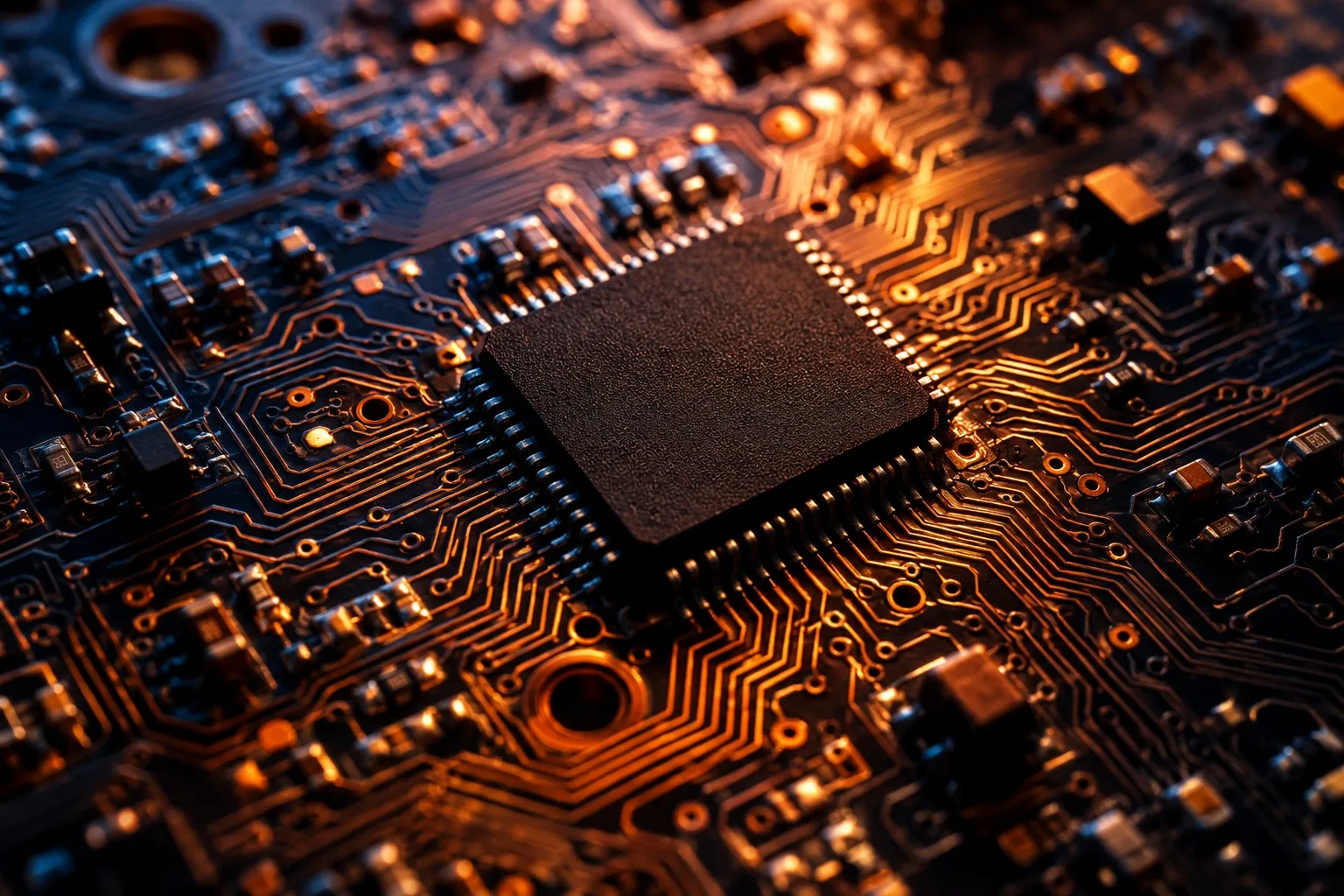
A microcontroller integrates a CPU core, memory, and peripheral hardware onto a single silicon die. Unlike a general-purpose microprocessor that relies on external RAM, storage, and peripheral controllers, a microcontroller is self-contained. This architecture makes it the backbone of industrial control systems, automotive electronics, and consumer devices.
Understanding how a microcontroller functions at the hardware level is essential for writing reliable firmware. High-level abstractions and libraries often hide memory management and register manipulation, but production-grade engineering requires a direct understanding of silicon behaviour.
Core Components and Memory Architecture
Every microcontroller consists of three primary functional blocks: the processor core, system memory, and peripheral interfaces. The processor executes instructions fetched from memory, performing arithmetic and logical operations. Memory is divided into non-volatile Flash memory, which holds the compiled program code, and volatile Static RAM (SRAM), which stores variables, stack frames, and dynamic data.
Microcontrollers typically use a Harvard architecture or a modified Harvard architecture. Unlike the von Neumann architecture, which shares a single bus for code instructions and data, Harvard architecture uses separate instruction and data buses. This allows the processor to fetch an instruction and read or write data simultaneously, improving execution speed and cycle efficiency.
Memory-Mapped Registers and the Volatile Keyword
Peripherals such as General Purpose Input/Output (GPIO) ports, timers, and analogue-to-digital converters (ADCs) are controlled through memory-mapped registers. The silicon designer assigns specific memory addresses to hardware control registers. Writing a binary value to a specific address configures pin modes, sets clock frequencies, or triggers transmission.
When accessing these memory locations in C or C++, engineers cast memory addresses to pointers. A common trap occurs when compiler optimisations strip away register reads or writes because the compiler does not detect variable changes within the local code scope. To prevent this, register pointers must be declared with the volatile qualifier. The volatile keyword forces the compiler to read directly from the physical memory address on every access rather than caching the value in a CPU register.
Timers and Interrupt-Driven Control
Real-time systems cannot rely on software delay loops to measure time or wait for external signals. Delay loops waste processor cycles and prevent the system from responding to urgent events. Microcontrollers resolve this using hardware timers and interrupt controllers.
Hardware timers count clock cycles independently of the main CPU execution. They can trigger an event, toggle output pins, or generate an interrupt when a counter reaches a target value. Interrupts pause the main execution thread and transfer control to an Interrupt Service Routine (ISR).
The Nested Vectored Interrupt Controller (NVIC) in ARM Cortex-M processors manages interrupt prioritisation. When multiple hardware interrupts fire simultaneously, the NVIC directs the CPU to execute the highest-priority ISR first. Once the ISR completes, the processor restores the CPU registers from the stack and resumes normal execution.
Serial Communication Protocols
Microcontrollers communicate with sensors, displays, and secondary chips using serial protocols. The three most prevalent protocols are UART, SPI, and I2C.
- UART (Universal Asynchronous Receiver-Transmitter): Point-to-point, asynchronous protocol requiring two data lines (TX and RX). It relies on predefined baud rates rather than a shared clock signal.
- SPI (Serial Peripheral Interface): Synchronous, full-duplex protocol using a shared clock line (SCK), Master Out Slave In (MOSI), Master In Slave Out (MISO), and Chip Select (CS) lines. SPI offers high data transfer rates over short physical distances.
- I2C (Inter-Integrated Circuit): Synchronous, multi-master protocol requiring only two bi-directional lines: Serial Data (SDA) and Serial Clock (SCL). It uses open-drain lines with pull-up resistors and addressing frames to target specific peripheral ICs.
Selecting the correct protocol depends on throughput requirements, pin availability, and physical layout constraints.
Common Pitfalls in Low-Level Firmware
Engineers developing low-level firmware frequently encounter issues stemming from hardware-software interactions:
- Floating Pins: Input pins left unconfigured or disconnected float between logic high and low due to electrostatic noise, causing unpredictable pin readings. Configuring internal pull-up or pull-down resistors stabilises input states.
- Blocking Operations in ISRs: Placing lengthy operations, print functions, or delays inside an ISR blocks other interrupts and breaks real-time responsiveness. ISRs should clear the interrupt flag, perform minimal state updates, and exit quickly.
- Shared Memory Race Conditions: Variables shared between an ISR and the main loop can be corrupted if the main loop is interrupted mid-write. Critical sections must be protected by temporarily disabling interrupts or using atomic operations.
At NEXISTEK, embedded systems training covers bare-metal programming, memory-mapped register manipulation, and peripheral driver development on modern 32-bit ARM Cortex-M microcontrollers. Understanding these fundamental engineering concepts enables developers to write deterministic, production-ready firmware.